Category Industrial data analytics

Continuous operation of IoT systems – Operating and Monitoring IoT Networks-2

Early detection of issues: Continuous monitoring of IoT networks enables organizations to detect issues early and resolve them before they turn into major problems. This helps prevent system downtime, reduce maintenance costs, and enhance the overall system performance.

Improved system performance: Real-time monitoring of IoT networks can identify performance bottlenecks and help optimize the system for better performance. This leads to faster response times, improved system reliability, and enhanced user experience.

Better decision-making: IoT monitoring solutions provide real-time data and insights that can inform effective decision-making. Organizations can use the data to make informed decisions that improve operational efficiency, reduce costs, and enhance overall business performance.

Enhanced security: Continuous monitoring of IoT networks helps identify security vulnerabilities and potential threats. This enables an organization to take proactive measures to prevent attacks and protect sensitive data, ensuring the safety and security of the system.

Predictive maintenance: Continuous monitoring of IoT networks can identify patterns and trends that can inform predictive maintenance. This helps an organization identify potential failures before they occur, reducing maintenance costs and increasing the overall lifespan of the system.

Scalability: Continuous monitoring solutions can scale to meet the needs of expanding IoT networks. This enables an organization to handle large volumes of data and maintain a comprehensive view of the system’s performance, even as the network expands.

On the other hand, it is important to understand how the monitoring framework is done over AWS and in general. In Figure 9.1, we can see how this framework can be visualized and stepped through for our needs:

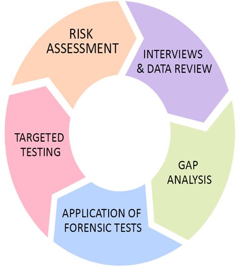
Figure 9.1 – IoT network monitoring framework

Here, we have the framework that we will walk through step by step to understand what each step encompasses:

Targeted testing: This step involves testing specific areas of the IoT network to identify potential vulnerabilities or weaknesses. Testing may involve performing a penetration test or using specialized tools to identify vulnerabilities in the network. In a smart home IoT network, targeted testing might involve using a network scanning tool such as Nmap to identify open ports on devices such as smart thermostats or security cameras.

Risk assessment: In this step, the results of the targeted testing are analyzed to identify potential risks and threats to the IoT network. A risk assessment helps to prioritize potential vulnerabilities based on their likelihood and potential impact on the network. After identifying vulnerabilities in the smart home network, a risk assessment could determine that an unpatched security camera poses a high risk due to its accessibility from the internet and the potential for it to be used as a gateway to access other devices on the network.

Interviews and data review: This step involves interviewing key stakeholders and reviewing data from various sources, such as system logs and incident reports. The goal is to gather additional information about potential vulnerabilities and risks to the IoT network. Interviews with the smart home’s residents could reveal that they are unaware of the need to regularly update device firmware. Reviewing system logs might show repeated attempts to access devices from unrecognized IP addresses, indicating potential security threats.

Gap analysis: This step involves comparing the results of the previous steps to the organization’s security policies and procedures. This helps to identify any gaps in the security posture of the IoT network and determine areas where improvements are needed. Comparing the current security measures of the smart home network with industry best practices might reveal gaps such as a lack of regular firmware updates, an absence of strong password policies, or a failure to segment the network to isolate critical devices from one another.

Application of forensic tests: The final step involves conducting forensic tests on the network to gather additional information about potential vulnerabilities and risks. Forensic tests may include analyzing system logs or performing a deep dive into specific areas of the network to identify potential issues. Forensic analysis of the smart home network could involve examining the security camera’s logs to trace back to the origin of unauthorized access attempts. It might also include a deep dive into network traffic to identify any unusual patterns that could indicate a breach or an ongoing attack.

By following these five steps, organizations can ensure that their IoT networks are monitored effectively and continuously, helping to minimize potential risks and threats and ensuring the overall security and efficiency of their networks.

Continuous operation of IoT systems – Operating and Monitoring IoT Networks-1

In today’s fast-paced digital landscape, maintaining the continuous operation of IoT networks is more critical than ever. IoT networks are being used in a wide range of industries, from manufacturing and logistics to healthcare and retail, to collect and process real-time data and automate processes. As such, even a brief downtime can result in significant losses in revenue, productivity, and customer satisfaction. Therefore, it is essential to ensure that IoT networks remain operational 24/7, with little to no disruption in service.

In this section, we will explore the concept of continuous operation in IoT networks, discussing the challenges and benefits of maintaining uptime, as well as the strategies and best practices for achieving this goal. We will cover topics such as redundancy and failover mechanisms, monitoring and alerting systems, regular maintenance and updates, automation, machine learning, and KPI tracking. By the end of this section, readers will have a solid understanding of the importance of continuous operation in IoT networks and the tools and strategies needed to achieve this goal.

Challenges and benefits of maintaining continuous operation

Maintaining continuous operation of monitoring solutions can be challenging, particularly in the context of IoT networks where the volume of data being generated and transmitted can be significant. The following are key challenges that need to be looked at:

Managing data volumes: The massive influx of data generated by IoT devices can be overwhelming for organizations. Managing and processing the data in real time becomes a challenge, and requires effective data management strategies to ensure that data is processed accurately and efficiently.

Ensuring data accuracy: IoT monitoring data must be reliable and accurate to enable effective decision-making. Any inaccuracies or inconsistencies must be identified promptly, and mechanisms must be in place to rectify them.

Integrating with existing systems: Integration of IoT monitoring solutions into the existing architecture can pose a challenge. An organization needs to ensure that IoT monitoring solutions are compatible with existing systems and that the data from different systems is integrated to provide a comprehensive view of the overall system performance.

Balancing monitoring with system performance: Monitoring solutions generate huge volumes of data, which can consume resources and impact system performance. Organizations must balance monitoring requirements with system performance and implement effective resource management to avoid any adverse impact.

Maintaining security: IoT monitoring systems must be safeguarded from cyberattacks, as they can become a gateway for attackers to gain access to sensitive data. Security protocols must be in place to ensure the safety of the monitoring systems and data.

The challenge of scalability: IoT networks are expanding rapidly, leading to an increase in the volume of data generated. Monitoring solutions must be scalable to handle the growing data volumes, and the monitoring infrastructure must be designed to ensure effective monitoring and management of the system.

Maintaining the continuous operation of IoT monitoring solutions brings several benefits to organizations, including the following:

Technical requirements – Operating and Monitoring IoT Networks

With the increasing number of connected devices and sensors, managing and monitoring IoT networks has become a critical task for organizations. Operating and monitoring IoT networks requires a comprehensive approach that includes continuous operations, setting key performance indicators (KPIs) such as the number of active users on an IoT network or the latency expected, setting/monitoring metrics to measure success, and utilizing monitoring capabilities both on-premises and on the cloud. In this chapter, we will delve into the critical aspects of operating and monitoring IoT networks. We will discuss the importance of continuous operations, exploring the challenges of keeping the system running 24/7 and techniques to ensure maximum uptime. Furthermore, we will explore the essential KPIs that organizations need to measure to ensure the success of their IoT projects, including reliability, scalability, and security.

We will examine the different monitoring capabilities available for IoT networks, including on-premises and cloud-based monitoring tools. Specifically, we will dive into the capabilities of Amazon Web Services (AWS) for monitoring IoT networks. By the end of this chapter, readers will have a comprehensive understanding of the best practices and tools for operating and monitoring IoT networks, enabling them to ensure the success of their IoT projects.

In this chapter, we’re going to cover the following main topics:

Continuous operation of IoT systems

Setting KPIs and the metrics for success

Monitoring capabilities on-premises and on the cloud

Practical – operating and monitoring a joke creator with IoT Greengrass

Technical requirements

This chapter will require you to have the following software ready for the practical. The software requirements may include items that you are already familiar with, as well as new software that you may need to acquire or install.

You will need the following software:

Diagram design software of your choice (e.g., Draw.io)

AWS account

OpenAI subscription (to use ChatGPT)

Arduino IDE

ChatGPT is built on the GPT-4 architecture, presenting a big advancement in the domain of natural language processing (NLP). This model has been trained on vast swathes of data, which allows it to generate coherent and contextually relevant textual outputs, simulating human-like conversation with impressive fluency and depth.

The ChatGPT API emerges as a pivotal bridge between different key pieces of hardware and software. The API allows developers to integrate the capabilities of ChatGPT into their own applications, platforms, or services. The implications for the Internet of Things (IoT) are profound due to this. Picture a world where your smart fridge not only tells you are out of milk but also engages in a nuanced conversation about dairy alternatives, their environmental impacts, and recipes you might try. By melding the ChatGPT API with IoT devices, we can create a seamless, intelligent, and interactive ecosystem that responds and converses with us, enhancing our daily experiences and decision-making processes. In this chapter, we will look at integrating this within one such practical.

You can access the GitHub folder for the code that is used in this chapter at https://github.com/PacktPublishing/IoT-Made-Easy-for-Beginners/tree/main/Chapter09/.

Working with the Arduino IDE – Designing for Interoperability

Interaction with the Telegram bot will be facilitated using the Universal Arduino Telegram Bot Library, a tool created by Brian Lough that simplifies access to the Telegram Bot API. We will ensure that our Arduino IDE has these libraries and procure them if not. Proceeding from here, we can follow the following steps:

First, we need to download the Universal Arduino Telegram Bot library. We can find it at https://github.com/witnessmenow/Universal-Arduino-Telegram-Bot/archive/master.zip.

We then need to include the library. We need to navigate to Sketch > Include Library > Add. Zip the library and add the library:

Figure 8.7 – Pop-up window to add in the Universal Arduino Telegram Bot library

Important note

You should not be installing the library with the Arduino Library Manager, as a deprecated version may be installed instead.

We then must install the ArduinoJson library. To do this, we navigate to Sketch > Include Library > Manage Libraries.

We then search for arduinojson and install its latest version:

Figure 8.8 – Adding in the ArduinoJson library

With the libraries installed, we can now prepare the hardware.

Hardware setup

We will connect the ESP32 to the PIR motion sensor according to the following diagram. It is a motion sensor that detects movement by sensing changes in infrared radiation emitted by warm objects, such as humans or animals, in its field of view:

Figure 8.9 – Circuit diagram for PIR motion sensor

On the PIR to the ESP32, we will connect the negative terminal to GND, the positive terminal to 5V, and the supply terminal to GPIO 27.

Coding it up

We are now ready to start coding up the necessary code to run the program on our Arduino IDE.

We first declare the necessary libraries for the program. The WiFi.h library is used to connect to the internet over Wi-Fi. The WiFiClientSecure.h library establishes a secure client connection to ensure the data communication is encrypted. The UniversalTelegramBot.h library is for controlling the bot on Telegram, and the ArduinoJson.h library handles the JSON data format used by the Telegram bot:
#include <ArduinoJson.h>
#include <UniversalTelegramBot.h>
#include <WiFiClientSecure.h>
#include <WiFi.h>

We then create a struct to hold our network credentials (SSID and password), and you need to replace the “YOUR_SSID_HERE” and “YOUR_PASSWORD_HERE” placeholder values with your own values. Afterward, a TelegramBot class is defined that encapsulates the functionality of the UniversalTelegramBot library, simplifying our use of it later in the code. After this, we instantiate a NetworkCredentials object with bot_token and chat_id values that you need to replace with the personalized token you received for your bot and the user ID you received for your telegram account respectively, wifi_client as an instance of WiFiClientSecure to handle secure connections, and telegramBot as an instance of our TelegramBot class using the bot token and the secure client:
typedef struct {
    const char* network_id = “YOUR_SSID_HERE”;
    const char* network_pass = “YOUR_PASSWORD_HERE”;
} NetworkCredentials;
class TelegramBot {
public:
    TelegramBot(const char* botToken, WiFiClientSecure& client) : bot(botToken, client) {}
    void sendMessage(const char* chatId, const char* msg) {
        bot.sendMessage(chatId, msg, “”);}
private:
    UniversalTelegramBot bot;};
NetworkCredentials networkCredentials;
const char* bot_token = “6344540752:AAHN_xoPfRipHbAf2d5cbceWLnYvxd2uRiI”;
const char* chat_id = “6394755694”;
WiFiClientSecure wifi_client;
TelegramBot telegramBot(bot_token, wifi_client);

Following that, we set up the PIR sensor pin and a Boolean flag to track whether motion is detected. The detectMotion function will be called whenever the sensor pin detects a rising voltage (that is, motion), setting movementDetected to true:
constexpr int PIR_SENSOR_PIN = 27;
volatile bool movementDetected = false;
void IRAM_ATTR detectMotion() {
    movementDetected = true;}

We then need to create a connectWiFi function that sets the ESP32 to operate in Station (STA) mode and then attempts to connect it to the Wi-Fi network using the credentials we provided earlier. It also sets the certificate root on the secure client. It then waits until the ESP32 is connected before continuing the program:
void connectWiFi() {
    WiFi.mode(WIFI_STA);
    WiFi.begin(networkCredentials.network_id, networkCredentials.network_pass);
    wifi_client.setCACert(TELEGRAM_CERTIFICATE_ROOT);
    while (WiFi.status() != WL_CONNECTED) {
        delay(500);}}

Finally, we create setup() and loop() functions. The setup() function initializes serial communication, sets the PIR sensor pin as an input with a pull-up resistor, and attaches an interrupt to it. It then connects to the Wi-Fi and sends a message indicating that the bot is active. The loop() function is the main loop of the program, which constantly checks if motion has been detected. If so, it sends a message and resets the flag:
void setup() {
    Serial.begin(115200);
    pinMode(PIR_SENSOR_PIN, INPUT_PULLUP);
   attachInterrupt(digitalPinToInterrupt(PIR_SENSOR_PIN), detectMotion, RISING);
    connectWiFi();
    telegramBot.sendMessage(chat_id, “Bot activated”);}
void loop() {
    if (movementDetected) {
        telegramBot.sendMessage(chat_id, “Motion detected!”);
        movementDetected = false;}}

As per usual, verify the code to ensure that you have entered everything correctly. Remember that there are four fields you must personally modify with your own information. If everything is done correctly, you should see the upload be successfully completed and your Telegram bot start churning messages after you have clicked Start on it.

And with that, we are ready to test our implementation.

Creating a chatbot – Designing for Interoperability

To receive messages sent from the ESP32 based on the motion caught by the motion sensor, we have to first create a chatbot on the Telegram app:

To start off, we need to download the Telegram app. We can go to Google Play or the App Store and download and install Telegram from there:

Figure 8.3 – Downloading the Telegram app from the App Store

Open Telegram after it has finished installing, search for Botfather, and click on it. Alternatively, you can also open the t.me/botfather link on your smartphone:

Figure 8.4 – Searching for BotFather on the Telegram app

You will then have a window open and be prompted to click the Start button. Click on it accordingly.

To create your bot, follow the steps by typing /newbot and then completing the required information such as the bot’s name and username. Upon successful creation of your bot, a message including a link and bot token will be sent to you. It’s crucial to save the bot token as it will be required for the ESP32 to communicate with the bot. Navigate to the link to get to your bot on Telegram and click Start to prepare to receive messages on your app:

Figure 8.5 – Typing in /newbot to create a new bot

With that, we have created our bot! Now, we need to get a Telegram user ID.

Getting a Telegram user ID

By obtaining your Telegram user ID, you can ensure that your bot only interacts with authorized users. The ESP32 can compare the sender ID of incoming messages to your user ID and either process the message or disregard it, depending on the match. This way, you can filter out any messages that are not from your Telegram account or other approved sources:

To locate IDBot in your Telegram account, either conduct a search through Telegram’s search bar at the top or access this link, t.me/myidbot, through your smartphone.

To obtain your user ID, initiate a conversation with IDBot and enter /getid. You will then receive a response containing your user ID, which should be saved for future reference in this tutorial:

Figure 8.6 – Entering in /getid to see your ID with IDBot

Now that we have obtained our user ID, we can start working on the Arduino segment of the practical.